

In the last update, progress on the tanks and bunker had reached the stage where the left tank had been successfully water tested. Attention now turned to the right hand tank, which has not been as straight forward since it has several extra features. There is a reinforcing plate attached to the tank in the cab to which is fixed the reversing lever bottom pivot pin and the reverser quadrant. A brace has also been fixed between this plate and the outer face of the tank to help resist the inevitable movements associated with the locomotive working. Another addition to this tank has been the fitting of a tube just inside the cab to carry the connection from the vacuum ejector down to the train pipe. This is in line with our intention of having vacuum train braking, as well as the air train braking originally fitted. Before the position of this tube could be finalised it was necessary to be sure of the availability of a suitable vacuum ejector. With the welding having been completed on this tank, it has also been successfully subjected to a water test. A time consuming job which still needs to be carried out on the tanks concerns the welding on of several hundred dummy rivet heads which will give the impression of the riveted construction present on the original locomotive. With both side tanks and the bunker now almost complete, they were set out in the correct positions so that work could commence on the cab. This will be assembled in the same way as the bunker using dome headed Allen screws to simulate rivets.

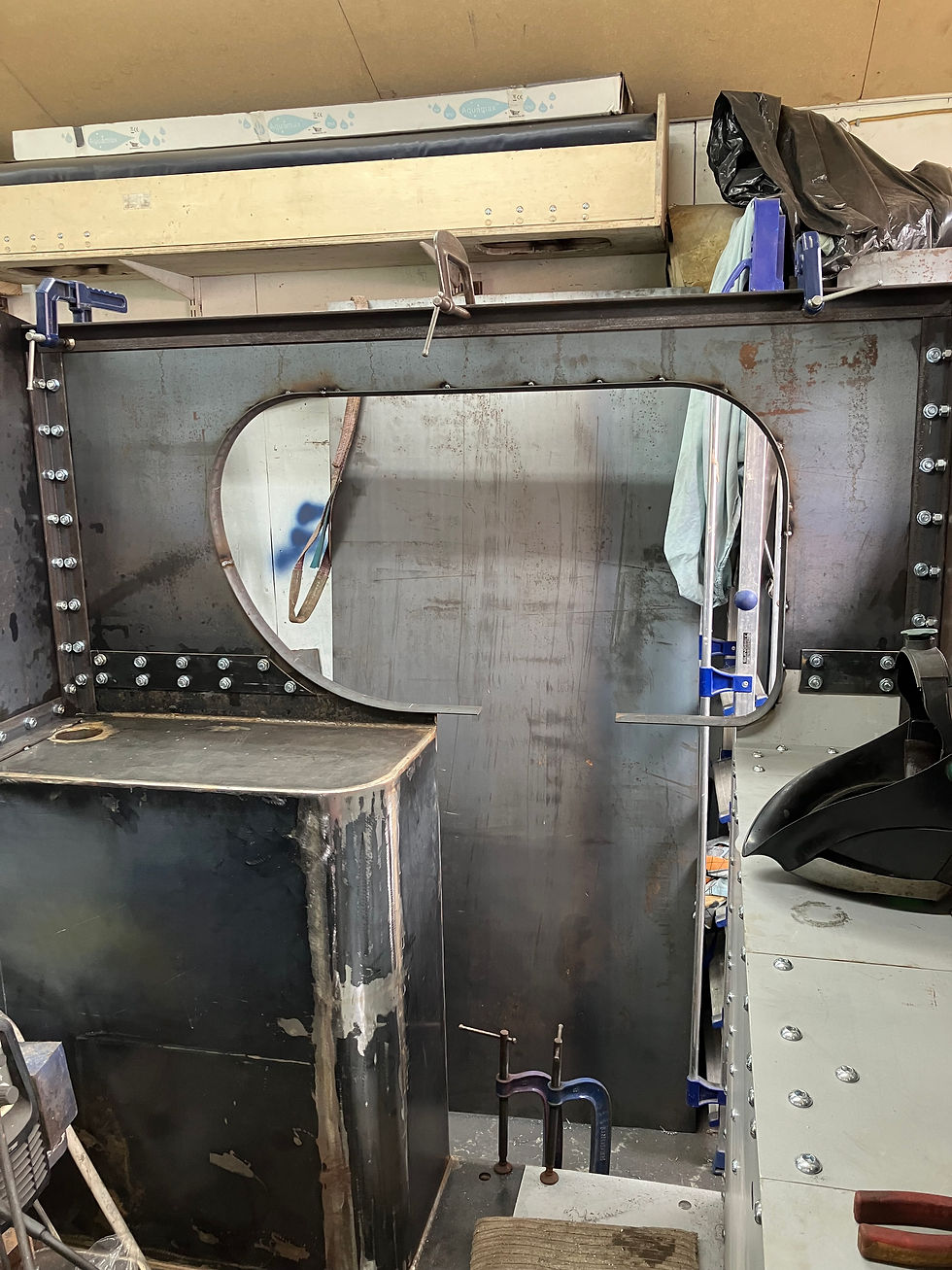
The right hand tank showing various clamps and other devices used to keep it straight during the welding process.

The right hand tank with the top now welded in place.

Fixing holes in the process of being drilled in the front and back of the cab.
As can be seen from the accompanying photographs, this has reached the stage of the cab components, with the exception of the roof, having been fastened to the tanks and bunker. Also fitted has been the beading around the cab side openings which will eventually support the top of the handrails. It is intended that the cab will be stripped, then sent for shot blasting and priming, prior to delivery to the workshop for assembly on the carrier frames, followed by the fitting of the cab roof. When we arrive at the stage of fitting the cab roof it is intended to incorporate a sliding ventilator. Although not many narrow gauge locomotives (including the original GOWRIE) seem to have been fitted with this feature, experience in operating other locomotives of similar size has led us to realise that this is a worthwhile addition, which will make operation in the hot summer months less oppressive. Over the next few pages you will see the tremendous progress that has been made over the last few months, firstly covering a sequence of the assembled fabrication of the bunker, tanks and cab components. This is followed by a considerable number of photographs showing the various stages in the assembly of the trailing bogie. This has involved assembling certain parts for trial fitting followed by dismantling for more machining to be carried out, then reassembled again to make sure that the parts fit together as they should, with the correct clearances.

Cab right hand side and back fastened into position on the bunker and side tank.
Another view of the right hand side of the cab with the front of the cab bolted into place.

The view that greeted us when the garage doors were opened.

The fully assembled tanks, bunker and cab components.

What we need now is the really important item that goes between the tanks!

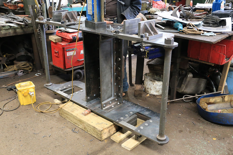
Final fitting of the trailing bogie hornguides.

Another view of the trailing bogie frames with the hornguides fitted.

Frames reassembled followed by the trial fitting of two axleboxes.

Trailing bogie stretcher with pivot casting fitted.

Trailing bogie stretcher in position.

Trailing bogie stretcher positioning being checked.

A view from the other end.

Bogie being set up for drilling the remainder of the fixing holes.
Drilling taking place.

Thrust face being machined on the fourth axlebox.

Trial fitting of the fourth axlebox.
Following on from the trailing bogie there are several pictures showing the latest patterns and castings that have been produced. These have been mainly concerned with the cylinders, i.e. the covers for the front, back and steam chests, plus those for the slide valves. The final illustrations show a recently acquired mechanical lubricator which will be used, after modification, to feed the cylinders. The last image shows the pattern which has just been received for the valve spindle guide castings.

Steam chest cover pattern.

Steam chest cover casting.

Slide valve pattern and casting showing opposite faces.

Front and rear cylinder cover patterns.

Front cylinder cover castings showing both faces.

Rear cylinder cover casting.

Our newly acquired mechanical lubricator for the cylinders.

Pattern for valve spindle guide.
Comments